ST Series AC Synchronous Alternators
Instructions for
Operation and Maintenance

The range of power ratings available in this series of alternators make them suitable for households, small holdings, and farms as well as supplying electricity for other static applications. These units employ a harmonic excitation winding to allow them to provide self excitation and a stable output without a separate voltage regulator. This simple system minimizes the complexity and has proven reliable in operation. ST alternators are designed for continuous duty operation within their power ratings. When driven at a constant rotational speed they generate current at a constant AC voltage and frequency. The internal connections may be changed to provide either 230V or 115V AC at 50Hz. Conversion between nominal voltages is a matter of changing contacts on a terminal strip inside the terminal box. Generators may be coupled to a static prime mover (driving internal combustion engine) either by a direct shaft to shaft coupling or by conventional belt and pulleys. The AC frequency of the output power is determined solely by the speed of rotation of the prime mover and the number of poles in the generator. Four pole generators must spin at 1500 RPM to generate 50Hz power. They can be driven either clockwise or anti clockwise to suit your application.
Please read the instructions completely and ensure that you understand them thoroughly before operating your ST alternator. This will allow you to operate your alternator correctly and achieve the longest and most reliable service from your unit.
Specifications for the ST Series generators are shown in the following table.

Construction
ST Series alternator are of the "rotating field" type of construction. In this type of alternator, the output power comes from windings that are held fixed in position on the motor frame (known as the stator) while an electrically generated magnetic field is rotated past the stator windings by turning the rotating assembly (known as the rotor). The rotor windings carry DC current obtained by rectifying a portion of the generators AC output. This exciting current is self generated, and is used in a manner which causes the output voltage to be self regulating to a large extent.
The construction of these alternators are intended to be drip proof – that is, a few drops of liquid onto the generator should not immediately cause damage. However, like all electrical equipment, the generator should be protected from damp conditions, immersion in water, or water dripping onto the alternator. The frame and end covers are manufactured from cast iron. The stator is built from high quality 0.5mm thick silicon steel laminations, wound with Class E temperature rated insulated wire. The rotor is wound with Class B temperature rated insulated wire. Overall, the alternator carries a protective class rating of IP 21. A schematic and details of the wiring are shown below.

The output frequency of the alternator is completely dependent on the rotational speed of the generator shaft. If accurate output frequency is required, then some means must be provided to accurately govern the speed of the prime mover which drives the alternator.
However, the output voltage is also dependent on the rotational speed of the prime mover as well as the amount of current in the field windings. If very accurate frequency of the output power is not necessary, as might be the case for incandescent lighting applications, it is possible to use the output voltage as an indicator of the proper rotational speed. All that is necessary is to regulate the speed of the prime mover so that the voltmeter indicates the rated voltage. Since the output voltage depends partially on the prime mover’s rotational speed, the output voltage provides a fairly accurate estimate of the rotational speed. The resulting frequency may not match commercial power line standards exactly, but the voltage will be correct and for applications such as incandescent lighting, correct voltage and close frequency is sufficient for reliable use.

If an exact adjustment of voltage is needed, you must set both the rotational speed and the current through the field windings. Remove the short connection strip between terminals F2R and R1 in the terminal box, and connect a rheostat (variable power resistor) between these two points. Set the prime mover speed to the exact required 1500rpm by means of a tachometer on the prime mover or a frequency meter on the output power. (Either method works equally well as the output frequency is controlled only by the prime mover rotational speed.) The output frequency will now be exactly 50Hz. Adjust the rheostat resistance to set the desired output voltage. Once the rheostat is adjusted in this manner with no load, it is generally unnecessary to readjust it for correct voltage under load. Rheostats should be rated for 10 ohms, 150W for ST1 through ST8 alternators, and 5 ohm, 200W for ST10 through ST20 alternators.
Automatic voltage regulators known as AVR's are available separately, please click here
Before Operating the Generator
Check to ensure that all the internal terminals are correctly connected for the desired output voltage.
Connect the output wiring to the output terminals U1 and U2 fed from the circuit breaker inside the terminal box of the alternator. Pay particular attention to making sure that the wires connected to the alternator output are of a heavy enough gauge to continually carry the maximum rated output current. Open the outer covering plate of the end cover and inspect the brushes to ensure that the brushes are making good contact with the slip rings in perfect central alignment. Ensure that the wiring to the load is correctly installed, secure, and that switches and fuses or circuit breakers rated for carrying and interrupting the rated power output are in place.
Switches and/or circuit breakers capable of isolating all electrical loads should be correctly installed, and should be in an open circuit position before starting the generator. Once the generator is up to speed and indicating the correct output voltage, the switches may be closed.
Starting and Stopping
To start
1, Start the prime mover engine operating and bring it up to the correct rated speed. When the rotational speed of the prime mover and generator near the rated speed, the alternator will start generating voltage by the self-excitation circuit.
2, Adjust the speed of the prime mover exactly if needed. Read the voltmeter on the unit. This should be at or near the rated value.
3, After a short warm up time under no load, the generator voltage will drop slightly. This is a consequence of the changes that increased temperature cause in the self excitation circuit. If needed, the voltage rheostat may be adjusted for a more precise output voltage after this initial warm up.
4, Once the frequency and voltage are acceptably adjusted, turn on the output switch(es) to the load(s).
To stop
1, Remove the load(s) from the output by opening the output switch(es).
2, Stop the prime mover.
Cautions:
Be very careful not to allow short circuits at the output of the generator. This can damage the rectifier diodes in the voltage regulating circuit.
Before stopping the generator, remove all output electrical loading first before turning off the prime mover. If you turn off the prime mover while the generator is under load, the resulting spin-down and gradually reducing electric fields may erase the residual magnetism in the rotor that allows the generator to start self excitation.
If the residual magnetism in the rotor is too weak to start self-excitation, the rotor will need to be re-magnetized.
Problems and Troubleshooting
First, verify that all internal and external connections are correct. Once this has been verified, if there is no voltage output then possible causes are:
Loss of residual magnetism
The rotor’s residual magnetism, which enables self-excitation, may be lost over time if the generator is unused for a long time or suddenly if the alternator’s prime mover is turned off while the electrical load is still connected to the generator.
To re-magnetize the rotor, flash connect a 12V storage battery to the field winding terminations F1 and F2 observing the polarity while the generator is rotating. Do not connect the battery in the reverse polarity and only connect the battery momentarily.
Rotational speed too slow
Measure the rotating speed of the prime mover with a tachometer and adjust it.
Open circuit or short circuit in the harmonic (self-excitation) winding
Replace the winding.
No DC output to the self excitation circuit (damaged rectifiers)
Replace the rectifier assembly.
Field winding is open or short circuited
Replace field winding.
Poor contact between the brush(es) and slip ring(s)
Clean the slip rings with fine emery cloth, and inspect or replace brushes or springs to ensure good contact. Good brush - slip ring alignment is essential for problem free operation. This should be periodically checked as part of a routine maintenance schedule.
Loose connection or poor contacts on the terminals
Clean and tighten the connections.
Maintenance and Repair
1, If the generator is to be stored, ensure that the storage place is dry and clean. If the generator is to be stored on an earth or concrete floor, place a wooden base under it to prevent contact between the generator and floor. Cover the generator with a water repellent tarpaulin or other water resistant covering to prevent water and dust from entering the generator.
2, Take steps to prevent water, dust, metal chips and shavings, and other foreign material from entering the generator.
3, Do not cover the generator with cloth, wood, paper, etc. while operating. The generator should have free, unimpeded air circulation to allow it to dissipate normal internal heat build up. The generator may be damaged by heat build up if it is covered during operation.
4, Do not overload the generator. Provide circuit breakers or other means to prevent this.
5, During operation, check the generator periodically for unusual sounds and/or sparks from the brushes and slip rings. Stop the generator immediately if such sounds or sparks are noticed, and then inspect and repair the generator.
6, Do not operate the generator in atmospheres that are very humid or dusty, or when there are combustible gasses in the area of the generator.
7, Remove and replace the grease in the ball and roller bearings after every 3000 hours of operation, or at least once per year. The bearing housing should normally be filled to about half its volume with grease – do not fill it more than half full.
Replace the grease only with a good grade of molybdenum disulphide lithium based grease. The maximum permissible temperature of the ball and roller bearings is 95C (203F).
Inspecting and Overhauling
The generator should be inspected at intervals of no more than six months.
1, Remove the end cover and clean out any dust that may have accumulated in the generator. The preferred method for this is to use compressed air at not more than 0.4kg/cm 2 (5.7 psi)
2, Clean the slip rings. Wipe the rings clean with a piece of coarse cloth lightly moistened with kerosene. Do not use waste yarn or other fibrous material. Once the slip ring surfaces are clean, wipe them dry with a dry cloth and check for correct alignment.
3, Inspect the bearings. Remove the outer covering of the bearing and determine whether the grease is at a sufficient level and clean. If the grease is dirty or contaminated, remove the old grease and replace with the correct level of fresh grease.
4, Inspect the brushes and spring assemblies for wear and tear. Replace worn out brushes and springs with new ones.
Necessary Precautions
When inspecting and overhauling the generator, follow these precautions:
1, Keep the disassembled parts in a suitable container to prevent loss or contamination.
2, Mark terminal leads before disconnecting them so they can be easily identified and replaced in the correct positions on reassembly.
3, Whenever the bearing covers are removed, take care to prevent contamination of the bearing with dirt and dust. Clean the surrounding area before opening the cover, and protect the bearing cover and bearing with clean paper.
4, When mounting a brush, make certain that its position is correct and that it makes good contact with the slip rings.
5, After the generator is properly installed, turn the rotor by hand to make sure that it moves freely.
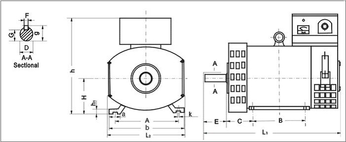
Dimensions and Mechanical Data

STC Series
Three-Phase AC
Synchronous Generator


To purchase one of these ST or STC alternators please click here for current prices and stock availability.


